English (UK)
  Français (FR)

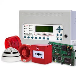
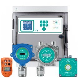

1 Analogue Loop 16 Zones with APOLLO protocol Addressable Fire Control Panel Kentec SYNCRO AS LITE LA81161M2

1 Analogue Loop 16 Zones with HOCHIKI protocol Addressable Fire Control Panel Kentec SYNCRO AS LITE LH81161M2

1 Analogue Loop 16 Zones + key with APOLLO protocol Addressable Fire Control Panel Kentec SYNCRO AS LITE LA80161M2
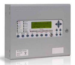
1 Analogue Loop 16 Zones + key with HOCHIKI protocol Addressable Fire Control Panel Kentec SYNCRO AS LITE LH80161M2
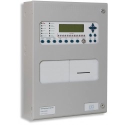
1 Analogue Loop 16 Zones with APOLLO Protocol Addressable Fire Control Panel Large Enclosure + Key & Printer Kentec SYNCRO AS A80161M3P

1 Analogue Loop 16 Zones with HOCHIKI Protocol Addressable Fire Control Panel Large Enclosure + Key & Printer Kentec SYNCRO AS H80161M3P

1 Analogue Loop 16 Zones with APOLLO Protocol Addressable Fire Control Panel Large Enclosure with Activation key Kentec SYNCRO AS A80161M3

1 Analogue Loop 16 Zones with APOLLO Protocol Addressable Fire Control Panel Large Enclosure Kentec SYNCRO AS A81161M3

1 Analogue Loop 16 Zones with HOCHIKI Protocol Addressable Fire Control Panel Large Enclosure with Activation key Kentec SYNCRO AS H80161M3

1 Analogue Loop 16 Zones with HOCHIKI Protocol Addressable Fire Control Panel Large Enclosure Kentec SYNCRO AS H81161M3

1 Analogue Loop 16 Zones with APOLLO Protocol Addressable Fire Control Panel Small Enclosure + Key Kentec SYNCRO AS A80161M2

1 Analogue Loop 16 Zones with HOCHIKI Protocol Addressable Fire Control Panel Small Enclosure + Key Kentec SYNCRO AS H80161M2